5G NR (New Radio) Technology
Several amazing things come to our mind when we hear about the words 5G NR, like Fast data speed, Mission critical communications, Massive Internet of Things, Low latency, Reduced battery power, Massive MIMO, Beam Management, autonomous driving and many more. Here we will discuss about all these new features of 5G NR technology in details.Table of Contents:
- 3GPP Specifications related to 5G NR
- 5G NR Basic Fundamentals/ Network Deployment Options
- Features/Specifications Comparison Between 4G LTE and 5G NR
- Key Features of 5G NR Technology
- 5G NR Frequency ranges and Operating Bands
- NR Scalable/Flexible Numerologies
- 5G NR Frame/Subframe/Slot Structure
- 5G NR Physical Resources: Resource Element/Block/Grid Structures
- EN-DC / 5G NR Dual Connectivity
- 5G NR RRC States
- 5G NR Transmitter and Receiver Chains
- 5G NR Downlink Channels and Signals
- 5G NR Uplink Channels and Signals
- 5G NR Control Resource Set (CORESET)
- 5G NR Beam Forming, Beam Scheduling and Beam Management
3GPP Specifications related to 5G NR:
Similar to LTE, 3G and other technologies, 5G NR technology also has many 3GPP specifications. There are tons of websites and papers about this technology. Sometimes it becomes difficult for the reader to find the right specification for a particular topic of interest. To help the readers, here we have collected this information in below table. For more details, please refer this 3GPP website link: "https://www.3gpp.org/".5G NR Radio Interface Protocol Architecture:
The 5G NR radio interface contains the Layer 1, 2 and 3. The Layer 1 (Physical Layer) specifications are defined in TS 38.200 series and 38.300 series describes the specification about Layers 2 and 3.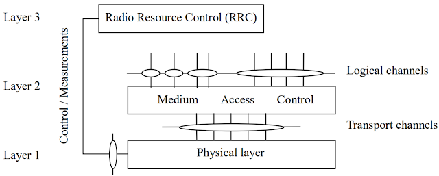
Figure: 5G NR Radio interface protocol architecture
The 5G NR radio interface protocol architecture around three layers; Layer 1, 2 and 3 is shown in above figure [Reference: 3GPP TS 38.201 ]. The Layer 1 (physical layer - PHY) interfaces with Layer 2 (Medium Access Control- MAC) and Layer 3 (Radio Resource Control- RRC). The information between physical layer and MAC layer is transferred over radio interface via transport channels and from MAC to Radio Link Control via Logical channels as shown in the figure.
5G NR Documents Relationship:
Usually readers face difficulties in finding the right documents for different layer of radio interfaces. Below figure shows a brief summary and interconnection between the physical layer and higher layer documents [Reference: 3GPP TS 38.201].
Figure: Relationships among physical layer documents
Back to Table of Contents [TOP]
5G Network Deployment Options:
There are multiple options 5G technology can be deployed. Based on the network infrastructure, they can be divided in two different categories as given below.
Back to Table of Contents [TOP]
5G Performance requirements for high data rates and traffic densities:
The performance requirements for high data rates and traffic densities are defined by 3GPP in 3GPP TS 22.261 as given in the following table.
Back to Table of Contents [TOP]

Back to Table of Contents [TOP]
Back to Table of Contents [TOP]
Back to Table of Contents [TOP]
The duration of downlink or uplink NR Frame is 10 ms long and it is calculated as Tf=(Δfmax.Nf/100).Tc. One frame consists of 10 Subframes of Tsf=(Δfmax.Nf/1000).Tc= 1 ms duration. Each frame is further divided into two equal sized half-frames 0 and 1. Half-frame 0 comprises subframes 0-4 and Half-frame 1 comprises subframes 5-9.
 Figure: 5G NR Frame and Subframe Structure
Below figure shows the timing relation between Uplink and Downlink frames. UE sends Uplink frame before downlink frame with an advance time TTA = (NTA + NTA,offset).Tc, where NTA and NTA,offset parameters are provided to the UE in the message n-TimingAdvanceOffset for the serving cell as given in 3GPP TS 38.213 document.
 Figure: Downlink and Uplink timing relation
Slots and OFDM symbols: For a given subcarrier spacing configuration [μ], slots are numbered as nμs ∈ {0, ...., Nslotsubframe,μ - 1} in increasing order within a subframe and nμs,f ∈ {0, ...., Nslotframe,μ - 1} within a frame. In one slot, there are Nslotframe,μ consecutive OFDM symbols depending on the cyclic prefix values as given in below table. The start of a subframe is aligned in time with the start of OFDM symbol in the same subframe.
OFDM symbols in a slot can be categorized as 'downlink', 'flexible', or 'uplink' symbols. A UE which does not support full-duplex communication, is not expected to transmit in the uplink (or downlink) earlier than NRx-TxTc (or NTx-RxTc) after the end of the last received downlink (or transmitted uplink) symbol in the same cell where NRx-TxTc and NTx-RxTc are given in below tables [Ref: 3GPP TS 38.211]. The numerology parameter μ and the cyclic prefix for a bandwidth part are obtained from the higher-layer parameter subcarrierSpacing and cyclicPrefix, respectively.
Back to Table of Contents [TOP]
NR Resource Grid (RG): Overview of the NR Resource Grid is given in below grid diagram. At the first look, it seems to be very similar to the LTE resource grid, but for NR, the actual physical dimension will be changed based on the selected carrier and numerology parameter (μ).
 For a given numerology and carrier, the size of the RG (number of subcarriers and OFDM symbols sets for DL or UL) and starting point at a common resource block are provided by higher-layer signalling. The carrier bandwidth is given by parameter carrierBandwidth and the starting position of the grid is given by parameter offsetToCarrier in the SCS-SpecificCarrier IE. The frequency location of a subcarrier is same as the center frequency of that carrier.
The higher-layer parameter txDirectCurrentLocation in the SCS-SpecificCarrier IE gives the location of the transmitter DC subcarrier in downlink side and txDirectCurrentLocation in the UplinkTxDirectCurrentBWP IE providest the location of transmitter DC subcarrier in uplink side.
For a given numerology and carrier, the size of the RG (number of subcarriers and OFDM symbols sets for DL or UL) and starting point at a common resource block are provided by higher-layer signalling. The carrier bandwidth is given by parameter carrierBandwidth and the starting position of the grid is given by parameter offsetToCarrier in the SCS-SpecificCarrier IE. The frequency location of a subcarrier is same as the center frequency of that carrier.
The higher-layer parameter txDirectCurrentLocation in the SCS-SpecificCarrier IE gives the location of the transmitter DC subcarrier in downlink side and txDirectCurrentLocation in the UplinkTxDirectCurrentBWP IE providest the location of transmitter DC subcarrier in uplink side.
Antenna Port: According to 3GPP TS 38.211-4.4.1, "An antenna port is defined such that the channel over which a symbol on the antenna port is conveyed can be inferred from the channel over which another symbol on the same antenna port is conveyed ". In other words, the shared or control channel data which is conveyed over an antenna port can be inferred from the channel over which reference symbols (DM-RS) if they are conveyed over same antenna port, resource, slot and same Physical resource block. Below is the summary of the antenna ports defined in 3GPP TS 38.211.
Resource Element (RE): Similar to LTE, Resource Element in NR is defined as the smallest physical resource, which consists of one subcarrier in time domain and corresponding one OFDM symbol in frequency domain. As shown in above Resource Grid diagram, RE is the smallest element represented by (k, l)th position in the above grid.
Resource Block (RB): Similar to LTE, RB in NR is defined as the block of 12 sub-carriers. More details on the way.
Unused Resource Block (URB): All the resource blocks in a channel bandwidth are not necessarily used for transmission. Some of the blocks are needed for the guardbands at both the edges of RF carrier to meet the out-of-band emission requirements. More details on the way.
Maximum Bandwidth in NR: Maximum possible carrier bandwidth in NR is limited to 275 RBs for any SCS. More details on the way.
Back to Table of Contents [TOP]
As discussed in the 5G NR Basic Fundamentals/ Network Deployment Options section, there are mainly two categories of 5G NR deployment - one is Standalone and other one is Non-Standalone. In this section, we will discuss more about the Non-standalone scenario needed for EN-DC (dual connectivity), it's functioning and requirements. In Non-standalone case, 5G radio access network will be deployed in inter-working with the existing LTE network. Let us first discuss about the need of this inter-working.
Need of Network Interworking: Let us think about the time when the 4G LTE network was initially evolved from 3G. At that time, 4G LTE cells were deployed with partial coverage. Seamless service was provided to the users through interworking of 4G LTE with 3G network using Core Network-level interworking solution. In this solution, 3G Core Network entity (Serving GPRS Support Node) directly interacts with the 4G LTE Core Network Entities e.g. MME and Serving Gateway.
4G-5G Interworking: There are two solutions for 4G LTE and 5G NR networks interworking: RAN-level interworking and CN-level interworking. For EN-DC connectivity, RAN-level interworking is necessary in Non-Standalone option, since 5G New Radio cannot be used without 4G LTE Radio. Below figure shows the RAN-level interworking of 4G LTE and 5G NR.
 Figure: RAN-level interworking of 4G LTE and 5G NR for EN-DC
Call Establishment in EN-DC using RAN level internetworking: Here are basic steps for the call flow of EN-DC.
Connection Establishment and Mobility: In RAN-level interworking, RRC message for control protocol is transmitted over the 4G LTE radio interface, which means the connection establishment and mobility of the UE is mainly controlled by the LTE eNB.
User Data Traffic: User data can be transmitted simultaneously over LTE eNB and 5G NR gNB (PDCP aggregation). Even though the user data is mostly transmitted over 5G NR, LTE radio interface always stays connected for connection and mobility management since LTE network provides larger coverage than 5G NR.
Upgrade Needed: 4G LTE and 5G NR interworking can be achieved by upgrading the existing LTE eNB and using them with the new 5G Core network. Upgrade in LTE eNB is done at EPC (Evolved Packet Core) level by increasing the gateway capacity in EPC. The new 5G NR features e.g. network slicing can be supported using 5G core.
Back to Table of Contents [TOP]
5G NR RRC Inactive State: In the legacy (3G or LTE), once UE is attached to the network, it can stay in RRC Idle or RRC connected state based on the user data activities. These two states of the UE are not sufficient or optimized for the new ultra-low latency and low power applications. Hence, a new state of UE is defined in 5G NR, known as Inactive state. Let us briefly discuss about Inactive state, it's need and benefits.
What is Inactive State and it's need: Inactive state is the intermediate state of the UE between Idle and Connected state. The main idea of introducing the Inactive state of the UE is that it can return to the Connected state as quickly and efficiently as possible. Whenever there is no data activity, UE should quickly transition to the Inactive state in order to save it's battery power.
During the transition to Inactive state, UE as well as RAN store all the necessary information so that later on it can resume the connection whenever needed. This stored information needed to restore the secured connection, is a set of parameters such as UE identifier, security information and RAN Notification Area (RNA) within which UE can move around without notifying the network.
When there is a need of connection for data exchange, the Inactive UE can initiate the resume procedure. This involves the restoration of the previously store information and then resume the connection without extensive signal with the core network e.g. without having the re-establishment of the security procedure. In this case, the UE sends an RRC resume request to the network. This request message includes the UE identifier and a security token to verify authenticity of the request.
During the resume procedure (Inactive to Connected state), the number of RRC messages exchanged between the UE and the RAN reduce to three (compare to seven in case of Idle to Connected state). Reduced signaling is possible during this resume transition by sending only the delta parameters (only changed parameters). This option is not available in the legacy Idle to Connected state transition scenario.
In summary, this resume procedure from Inactive to Connected state is similar to the hibernate (sleep) state of a computer where user can pause a work and resume later without going through the long and tedious start-up procedure again. The need for the Inactive state of a UE arises with the growing field of the Machine-type Communication and other 5G applications such as Ultra-reliable low-latency communication (URLLC) and Enhanced Mobile Broadband (eMBB). The key benefits of introducing the Inactive state of the UE are the significantly reduced latency and optimized battery consumption of the UE.
5G NR RRC States and Transitions: As discussed above, 5G NR has three different RRC states: RRC IDLE, RRC INACTIVE and RRC CONNECTED as shown in the figure below.

UE transitioned between different states as summarized below.
Back to Table of Contents [TOP]
5G NR Basic Fundamentals:
Before going into details, let us briefly discuss about the basic fundamentals of 5G NR and their network deployment options.5G Network Deployment Options:
There are multiple options 5G technology can be deployed. Based on the network infrastructure, they can be divided in two different categories as given below.
-
Standalone (SA) : Standalone option consists of only one generation of radio technology, i.e. only 4G LTE or only NR technology. Below are some options for standalone scenario.

Non-standalone(NSA): Non standalone option consists of multiple generations of radio technologies, i.e. 4G LTE and NR technologies together. Below are some options for non-standalone scenario.

In non-standalone case, most common and favorable option is Option 3. The initial deployment of 5G technology will be using either NSA option 3 or SA option 2 since most of the standardization of these options have already been studied and completed. In non-standalone option 3, eNB (eNodeB for LTE) work as master node and gNB (gNodeB) as the secondary node. The NSA option 3 is the preferred option since it is the leverage of existing 4G/LTE deployment and can be brought to the market quickly with some modifications to the existing 4G/LTE network. This option will directly support the existing 4G/LTE devices and 5G devices need to support the NR protocols. For this option, 5G capable devices can be developed quickly. Since option 3 does not introduce new 5G Core, this may not be the optimized for new 5G use cases and hence there will be further scope of optimizations.
Back to Table of Contents [TOP]
Features/Specifications Comparison Between 4G LTE and 5G NR ( 5g nr vs lte):
Here is the comparison between LTE and NR features/specifications for a quick view.5G Performance requirements for high data rates and traffic densities:
The performance requirements for high data rates and traffic densities are defined by 3GPP in 3GPP TS 22.261 as given in the following table.
| Scenario | Experienced data rate (DL) | Experienced data rate (UL) | Area traffic capacity (DL) | Area traffic capacity (UL) | Overall user density |
|---|---|---|---|---|---|
| Urban | 50 Mbps | 25 Mbps | 100 Gbps/KM2 | 50 Gbps/KM2 | 10,000 KM2 |
| Rural | 50 Mbps | 25 Mbps | 1 Gbps/KM2 | 500 Gbps/KM2 | 100 KM2 |
| Indoor Hotspot | 1 Gbps | 500 Mbps | 15 Tbps/KM2 | 2 Tbps/KM2 | 250,000 KM2 |
| Dense Urban | 300 Mbps | 50 Mbps | 750 Gbps/KM2 | 125 Gbps/KM2 | 25,000 KM2 |
| High Speed Vehicle | 50 Mbps | 25 Mbps | 100 Gbps/KM2 | 50 Gbps/KM2 | 4000 KM2 |
Key Features of 5G NR Technology:
There are many new features available in 5G which make it more popular and attractive technology in the current time. Some of the key features are given below.- Frequency Band Support: 5G supports higher and wider frequency band. Mainly two different frequency ranges are allocated: Frequency Range 1 (FR1) and Frequency Range 2 (FR2). Frequncy range of FR1 (also known as Sub-6GHz Band) is between 410MHz-7.125GHz and for FR2 is between 24.25GHz-52.6GHz. These frequency bands are based on 3GPP Release-16, but may change in future. Please click here for more details.
- 5G supports wider bandwidth (BW) per component carrier. In FR1 range, it supports upto 100MHz BW, and in FR2, it supports upto 400MHz BW, where as LTE supports a maximun of 20MHz BW per component carrier.
- Self Contend Slot Structure: 5G supports a self contend slot structure, which means an immediate HARQ feedback can be sent in the same slot as the data. This will provide the performance benefits in latency and throughput.

- Low Latency and High Reliability: As shown in above figure, 5G NR slot structure is very flexible and self-contained. It delivers significantly lower latency than LTE due to its faster UL/DL turn-around support. This slot structure includes UL/DL scheduling, data, SRS (Sounding Reference Signal) and acknowledgement in the same slot which makes 5G NR a good candidate for more reliable communication.
- Scalable Numerology : 5G supports multiple numerologies (different subcarrier spacings, Cyclic Prefix, slot length) with scaling. Click here for more details about Scalable Numerology.
- Forward Compatibility : 5G technology will be deployed in multiple phases with an evolution of current 4G (LTE) networks and the addition of a new radio access technology known as New Radio (NR). 5G technology is designed for forward compatibility. It uses self contained transmission, i.e. the data transmitted in a slot and a beam is decodable independently to the other slots or beam data.
5G transmissions are self confined in frequency and time domains in such a way that any new types of transmissions can be included in parallel with legacy transmissions in the future.
- Advanced Channel Coding schemes: 5G uses two capacity-achieving channel coding schemes of low-density parity-check (LDPC ) codes and Polar codes. LDPC codes are used for user data and the polar codes are used for for control information. LDPC codes are very powerful and have good error correcting capability. They are designed to support high throughput, a variable code rate and length.
On the other hand, 5G polar codes are designed to perform well with short block length and to address the latency issue of successive cancellation decoding.
- LTE NR Dual Connectivity: Non-Standalone (NSA) mode is the preferred option for the initial phase of 5G deployment. Initially, 5G mobile services will be provided primarily in 4G LTE networks via UEs that support dual connectivity to 4G LTE as well as 5G NR base stations at the same time. To enable dual connectivity, 4G LTE infrastructure will be used to connect the user to a 5G NR base station (gNodeB). More details about the LTE NR dual connectivity can be found in EN-DC section.
- Support of Dynamic TDD: 5G NR supports Dynamic Time Division Duplex (Dynamic TDD), which is one of the promising methods to improve the spectral efficiency of the wireless networks. User traffic can be handled more efficiently using dynamic TDD by changing the direction of uplink (UL) or downlink (DL) transmission dynamically.
Along with many advantages, dynamic TDD has some downsides as well. It may introduce additional cross-link interference (DL-to-UL and UL-to-DL interferences) which can degrade the system performance and hence, it needs extra care in resource management.
- New RRC Inactive State Support : Similar to the legacy technologies (3G, LTE etc.), in 5G NR also, a UE can move to different RRC states to optimize the battery consumption and other network resources. In addition to the existing RRC states, 5G NR supports a new RRC state known as RRC Inactive state. For more details about this new RRC Inactive state, please refer the "5G NR RRC States" section.
- Dynamic Spectrum Sharing: Details will come soon.
- Reduced Power Consumption : Details will come soon.
- Enhanced Multiple Antenna Techniques : Details will come soon.
- Other Improvements : Details will come soon.
Back to Table of Contents [TOP]
5G NR Frequency Ranges and Operating Bands:
The Frequency ranges and operating bands given in this section are based on the operating bands and channel bandwidths defined in release-16 of 3GPP spec 38.104. New operating bands and channel bandwidths may be defined in future releases based on the new developments in this area.5G NR Frequency Ranges:
The frequency ranges (FR1 and FR2) in which new 5G NR can operate are given in the below table based on the release-16.| NR Range Category | Corresponding Frequency Range |
|---|---|
| FR1 | 410 MHz – 7125 MHz |
| FR2 | 24250 MHz – 52600 MHz |
5G NR Operating Bands:
The operating bands (BS receive / UE transmit) for 5G NR FR1 and FR2 ranges are given in below two tables.| 5G NR Operating Band | Uplink Operating Band FUL,Low – FUL,High | Downlink Operating Band FDL,Low – FDL,High | Duplex Mode |
|---|---|---|---|
| n1 | 1920 MHz – 1980 MHz | 2110 MHz – 2170 MHz | FDD |
| n2 | 1850 MHz – 1910 MHz | 1930 MHz – 1990 MHz | FDD |
| n3 | 1710 MHz – 1785 MHz | 1805 MHz – 1880 MHz | FDD |
| n5 | 824 MHz – 849 MHz | 869 MHz – 894 MHz | FDD |
| n7 | 2500 MHz – 2570 MHz | 2620 MHz – 2690 MHz | FDD |
| n8 | 880 MHz – 915 MHz | 925 MHz – 960 MHz | FDD |
| n12 | 699 MHz – 716 MHz | 729 MHz – 746 MHz | FDD |
| n14 | 788 MHz – 798 MHz | 758 MHz – 768 MHz | FDD |
| n18 | 815 MHz – 830 MHz | 860 MHz – 875 MHz | FDD |
| n20 | 832 MHz – 862 MHz | 791 MHz – 821 MHz | FDD |
| n25 | 1850 MHz – 1915 MHz | 1930 MHz – 1995 MHz | FDD |
| n26 | 814 MHz – 849 MHz | 859 MHz – 894 MHz | FDD |
| n28 | 703 MHz – 748 MHz | 758 MHz – 803 MHz | FDD |
| n29 | N/A | 717 MHz – 728 MHz | SDL |
| n30 | 2305 MHz – 2315 MHz | 2350 MHz – 2360 MHz | FDD |
| n34 | 2010 MHz – 2025 MHz | 2010 MHz – 2025 MHz | TDD |
| n38 | 2570 MHz – 2620 MHz | 2570 MHz – 2620 MHz | TDD |
| n39 | 1880 MHz – 1920 MHz | 1880 MHz – 1920 MHz | TDD |
| n40 | 2300 MHz – 2400 MHz | 2300 MHz – 2400 MHz | TDD |
| n41 | 2496 MHz – 2690 MHz | 2496 MHz – 2690 MHz | TDD |
| n48 | 3550 MHz – 3700 MHz | 3550 MHz – 3700 MHz | TDD |
| n50 | 1432 MHz – 1517 MHz | 1432 MHz – 1517 MHz | TDD |
| n51 | 1427 MHz – 1432 MHz | 1427 MHz – 1432 MHz | TDD |
| n53 | 2483.5 MHz –2495 MHz | 2483.5 MHz–2495 MHz | TDD |
| n65 | 1920 MHz – 2010 MHz | 2110 MHz – 2200 MHz | FDD |
| n66 | 1710 MHz – 1780 MHz | 2110 MHz – 2200 MHz | FDD |
| n70 | 1695 MHz – 1710 MHz | 1995 MHz – 2020 MHz | FDD |
| n71 | 663 MHz – 698 MHz | 617 MHz – 652 MHz | FDD |
| n74 | 1427 MHz – 1470 MHz | 1475 MHz – 1518 MHz | FDD |
| n75 | N/A | 1432 MHz – 1517 MHz | SDL |
| n76 | N/A | 1427 MHz – 1432 MHz | SDL |
| n77 | 3300 MHz – 4200 MHz | 3300 MHz – 4200 MHz | TDD |
| n78 | 3300 MHz – 3800 MHz | 3300 MHz – 3800 MHz | TDD |
| n79 | 4400 MHz – 5000 MHz | 4400 MHz – 5000 MHz | TDD |
| n80 | 1710 MHz – 1785 MHz | N/A | SUL |
| n81 | 880 MHz – 915 MHz | N/A | SUL |
| n82 | 832 MHz – 862 MHz | N/A | SUL |
| n83 | 703 MHz – 748 MHz | N/A | SUL |
| n84 | 1920 MHz – 1980 MHz | N/A | SUL |
| n86 | 1710 MHz – 1780 MHz | N/A | SUL |
| n89 | 824 MHz – 849 MHz | N/A | SUL |
| n90 | 2496 MHz – 2690 MHz | 2496 MHz – 2690 MHz | TDD |
| n91 | 832 MHz – 862 MHz | 1427 MHz – 1432 MHz | FDD** |
| n92 | 832 MHz – 862 MHz | 1432 MHz – 1517 MHz | FDD** |
| n93 | 880 MHz – 915 MHz | 1427 MHz – 1432 MHz | FDD** |
| n94 | 880 MHz – 915 MHz | 1432 MHz – 1517 MHz | FDD** |
| n95* | 2010 MHz – 2025 MHz | N/A | SUL |
| Note: | * The band n95 is applicable in China only. ** Variable duplex operation not enabled by the network. | ||
| Operating Band of 5G NR | Uplink and Downlink Operating Band FUL,Low – FUL,High FDL,Low – FDL,High | Duplex Mode |
|---|---|---|
| n257 | 26500 MHz – 29500 MHz | TDD |
| n258 | 24250 MHz – 27500 MHz | TDD |
| n260 | 37000 MHz – 40000 MHz | TDD |
| n261 | 27500 MHz – 28350 MHz | TDD |
Back to Table of Contents [TOP]
NR Scalable/Flexible Numerologies:
5G NR is planned to support many many new features/applications such as extreme data download speeds, very low latency applications like remote medical surgery, ultra-low power devices, massive internet of things and so on. NR Scalable/Flexible Numerologies plays a crucial role to support these new features. Below are few key points of the scalable numerology.- Scalable Subcarrier Spacing: LTE has a fixed subcarrier spacing of 15KHz, but this is no more fixed in case of NR. In NR, subcarrier spacing scales with numerology as 2μ x 15 kHz to serve different requirements/services. The subcarrier spacings of 15, 30, and 60 kHz will be used for the lower frequency bands, and 60, 120, and 240 kHz for the higher frequency bands.
- Number of Slots in NR: Number of slots in NR frame increases with the increase in the numerology [μ]. Similar to LTE each frame is 10 ms long and has 10 subframes of 1 ms each. Each slot has 14 symbols for normal CP and 12 symbols for extended CP. Slot length scales with the numerology (=1 ms/2μ) and subcarrier spacing as shown in the table below. For more details about frame/subframe/slot structure, please click here.
| Numerology [ μ ] | Subcarrier Spacing: Δf=2μx15 KHz | Number of slots per subframe | Slot Length =1 ms/2μ |
|---|---|---|---|
| 0 | 15 KHz | 1 | 1 ms |
| 1 | 30 KHz | 2 | 500 μs |
| 2 | 60 KHz | 4 | 250 μs |
| 3 | 120 KHz | 8 | 125 μs |
- Introduction of Mini-slots: A standard slot of 1 ms has 14 OFDM symbols, but in NR, mini-slots are introduced which can have 7, 4, or 2 OFDM symbols. Mini-slots make NR more attractive and useful for very low latency applications. Mini-slots also play important role in coexistence of LTE-NR and also in beamforming.
- Dynamic DL and UL slots configuration In NR, link direction (DL or UL) can be dynamically changed for each OFDM symbol within the slot which allows the network to balance its DL and UL traffic dynamically.
- Concept of Bandwidth Parts: Bandwidth Parts (BWPs) is a new concept introduced in NR. It is a subset of contiguous common physical resource blocks (PRBs). Unlike LTE which can have a maximum bandwidth of 20 MHz, here NR can have a maximum bandwidth of 100 MHz for one carrier. With BWPs, bigger carrier bandwidths can be subdivided in several parts and can be used for different services. Each BWP can have its own numerology and can be configured independently based on the requirements. This feature provides more flexibility in assigning the resources and enables the network/ devices to use its spectrum/ power more efficiently.
Back to Table of Contents [TOP]
5G NR Frame/Subframe/Slot Structures:
Before going into details of the frame structure, let us look at the values of some basic parameters related to frames and subframes as defined in 3GPP TS 38.211 document. First, the size of various fields in the time domain is expressed in time units . The constant k=Ts/Tc=64 where .The duration of downlink or uplink NR Frame is 10 ms long and it is calculated as Tf=(Δfmax.Nf/100).Tc. One frame consists of 10 Subframes of Tsf=(Δfmax.Nf/1000).Tc= 1 ms duration. Each frame is further divided into two equal sized half-frames 0 and 1. Half-frame 0 comprises subframes 0-4 and Half-frame 1 comprises subframes 5-9.

Below figure shows the timing relation between Uplink and Downlink frames. UE sends Uplink frame before downlink frame with an advance time TTA = (NTA + NTA,offset).Tc, where NTA and NTA,offset parameters are provided to the UE in the message n-TimingAdvanceOffset for the serving cell as given in 3GPP TS 38.213 document.

Slots and OFDM symbols: For a given subcarrier spacing configuration [μ], slots are numbered as nμs ∈ {0, ...., Nslotsubframe,μ - 1} in increasing order within a subframe and nμs,f ∈ {0, ...., Nslotframe,μ - 1} within a frame. In one slot, there are Nslotframe,μ consecutive OFDM symbols depending on the cyclic prefix values as given in below table. The start of a subframe is aligned in time with the start of OFDM symbol in the same subframe.
| Numerology [ μ ] | Nsymbslot | Nslotframe,μ | Nslotsubframe,μ | Cyclic Prefix |
|---|---|---|---|---|
| 0 | 14 | 10 | 1 | Normal |
| 1 | 14 for Normal CP, 12 for Extended CP | 20 | 2 | Normal, Extended |
| 2 | 14 | 40 | 4 | Normal |
| 3 | 14 | 80 | 8 | Normal |
| 4 | 14 | 160 | 16 | Normal |
OFDM symbols in a slot can be categorized as 'downlink', 'flexible', or 'uplink' symbols. A UE which does not support full-duplex communication, is not expected to transmit in the uplink (or downlink) earlier than NRx-TxTc (or NTx-RxTc) after the end of the last received downlink (or transmitted uplink) symbol in the same cell where NRx-TxTc and NTx-RxTc are given in below tables [Ref: 3GPP TS 38.211]. The numerology parameter μ and the cyclic prefix for a bandwidth part are obtained from the higher-layer parameter subcarrierSpacing and cyclicPrefix, respectively.
| Transition time | Frequency Range FR1 | Frequency Range FR2 |
|---|---|---|
| NTx-Rx | 25600 | 13792 |
| NRx-Tx | 25600 | 13792 |
Back to Table of Contents [TOP]
5G NR Physical Resources: Resource Element/Block/Grid Structures:
In case of 5G NR, Resource Element, Resource Block and Resource Grid are also defined similar to that of LTE. Before going into their details, let us first have a look at NR resource grid structure.NR Resource Grid (RG): Overview of the NR Resource Grid is given in below grid diagram. At the first look, it seems to be very similar to the LTE resource grid, but for NR, the actual physical dimension will be changed based on the selected carrier and numerology parameter (μ).

Antenna Port: According to 3GPP TS 38.211-4.4.1, "An antenna port is defined such that the channel over which a symbol on the antenna port is conveyed can be inferred from the channel over which another symbol on the same antenna port is conveyed ". In other words, the shared or control channel data which is conveyed over an antenna port can be inferred from the channel over which reference symbols (DM-RS) if they are conveyed over same antenna port, resource, slot and same Physical resource block. Below is the summary of the antenna ports defined in 3GPP TS 38.211.
| Antenna Ports | Uplink Channel/ Signal |
|---|---|
| Antenna ports starting with 0 | For DMRS for PUSCH |
| Antenna ports starting with 1000 | For SRS, PUSCH |
| Antenna ports starting with 2000 | For PUCCH |
| Antenna port 4000 | For PRACH |
| Antenna Ports | Downlink Channel/ Signal |
|---|---|
| Antenna ports starting with 1000 | For PDSCH |
| Antenna ports starting with 2000 | For PDCCH |
| Antenna ports starting with 3000 | For CSI Reference Signal |
| Antenna ports starting with 4000 | For SS/PBCH block transmission |
Resource Element (RE): Similar to LTE, Resource Element in NR is defined as the smallest physical resource, which consists of one subcarrier in time domain and corresponding one OFDM symbol in frequency domain. As shown in above Resource Grid diagram, RE is the smallest element represented by (k, l)th position in the above grid.
Resource Block (RB): Similar to LTE, RB in NR is defined as the block of 12 sub-carriers. More details on the way.
Unused Resource Block (URB): All the resource blocks in a channel bandwidth are not necessarily used for transmission. Some of the blocks are needed for the guardbands at both the edges of RF carrier to meet the out-of-band emission requirements. More details on the way.
Maximum Bandwidth in NR: Maximum possible carrier bandwidth in NR is limited to 275 RBs for any SCS. More details on the way.
Back to Table of Contents [TOP]
EN-DC / 5G NR Dual Connectivity:
The EN-DC term stands for E-UTRA-NR (new radio) Dual Connectivity which was initially introduced in 3GPP Release 15. This feature allows a mobile device /User Equipment to communicate with 4G LTE and 5G NR base stations simultaneously via tight inter-working between two networks.As discussed in the 5G NR Basic Fundamentals/ Network Deployment Options section, there are mainly two categories of 5G NR deployment - one is Standalone and other one is Non-Standalone. In this section, we will discuss more about the Non-standalone scenario needed for EN-DC (dual connectivity), it's functioning and requirements. In Non-standalone case, 5G radio access network will be deployed in inter-working with the existing LTE network. Let us first discuss about the need of this inter-working.
Need of Network Interworking: Let us think about the time when the 4G LTE network was initially evolved from 3G. At that time, 4G LTE cells were deployed with partial coverage. Seamless service was provided to the users through interworking of 4G LTE with 3G network using Core Network-level interworking solution. In this solution, 3G Core Network entity (Serving GPRS Support Node) directly interacts with the 4G LTE Core Network Entities e.g. MME and Serving Gateway.
4G-5G Interworking: There are two solutions for 4G LTE and 5G NR networks interworking: RAN-level interworking and CN-level interworking. For EN-DC connectivity, RAN-level interworking is necessary in Non-Standalone option, since 5G New Radio cannot be used without 4G LTE Radio. Below figure shows the RAN-level interworking of 4G LTE and 5G NR.

Call Establishment in EN-DC using RAN level internetworking: Here are basic steps for the call flow of EN-DC.
- UE sends an ATTACH request to the LTE network. Once the UE attached to the LTE network, it signals the network that it wants to simultaneously connect to 5G network also.
- The Core netwrk check for the UE capability and authentication.
- The LTE eNB then activates the bearer on the 5G NR network.
- Finally, UE is connected to 4G LTE as well as 5G NR network simultaneously.
Connection Establishment and Mobility: In RAN-level interworking, RRC message for control protocol is transmitted over the 4G LTE radio interface, which means the connection establishment and mobility of the UE is mainly controlled by the LTE eNB.
User Data Traffic: User data can be transmitted simultaneously over LTE eNB and 5G NR gNB (PDCP aggregation). Even though the user data is mostly transmitted over 5G NR, LTE radio interface always stays connected for connection and mobility management since LTE network provides larger coverage than 5G NR.
Upgrade Needed: 4G LTE and 5G NR interworking can be achieved by upgrading the existing LTE eNB and using them with the new 5G Core network. Upgrade in LTE eNB is done at EPC (Evolved Packet Core) level by increasing the gateway capacity in EPC. The new 5G NR features e.g. network slicing can be supported using 5G core.
Back to Table of Contents [TOP]
5G NR RRC States:
Similar to the legacy technologies (3G, LTE etc.), in 5G NR also, a UE can move to different RRC states to optimize the battery consumption and other network resources. In 5G NR, a new RRC state is added, which is discussed below in more details.5G NR RRC Inactive State: In the legacy (3G or LTE), once UE is attached to the network, it can stay in RRC Idle or RRC connected state based on the user data activities. These two states of the UE are not sufficient or optimized for the new ultra-low latency and low power applications. Hence, a new state of UE is defined in 5G NR, known as Inactive state. Let us briefly discuss about Inactive state, it's need and benefits.
What is Inactive State and it's need: Inactive state is the intermediate state of the UE between Idle and Connected state. The main idea of introducing the Inactive state of the UE is that it can return to the Connected state as quickly and efficiently as possible. Whenever there is no data activity, UE should quickly transition to the Inactive state in order to save it's battery power.
During the transition to Inactive state, UE as well as RAN store all the necessary information so that later on it can resume the connection whenever needed. This stored information needed to restore the secured connection, is a set of parameters such as UE identifier, security information and RAN Notification Area (RNA) within which UE can move around without notifying the network.
When there is a need of connection for data exchange, the Inactive UE can initiate the resume procedure. This involves the restoration of the previously store information and then resume the connection without extensive signal with the core network e.g. without having the re-establishment of the security procedure. In this case, the UE sends an RRC resume request to the network. This request message includes the UE identifier and a security token to verify authenticity of the request.
During the resume procedure (Inactive to Connected state), the number of RRC messages exchanged between the UE and the RAN reduce to three (compare to seven in case of Idle to Connected state). Reduced signaling is possible during this resume transition by sending only the delta parameters (only changed parameters). This option is not available in the legacy Idle to Connected state transition scenario.
In summary, this resume procedure from Inactive to Connected state is similar to the hibernate (sleep) state of a computer where user can pause a work and resume later without going through the long and tedious start-up procedure again. The need for the Inactive state of a UE arises with the growing field of the Machine-type Communication and other 5G applications such as Ultra-reliable low-latency communication (URLLC) and Enhanced Mobile Broadband (eMBB). The key benefits of introducing the Inactive state of the UE are the significantly reduced latency and optimized battery consumption of the UE.
5G NR RRC States and Transitions: As discussed above, 5G NR has three different RRC states: RRC IDLE, RRC INACTIVE and RRC CONNECTED as shown in the figure below.

UE transitioned between different states as summarized below.
- After powering up, the UE first attaches to the network.
- Once the UE is attached to the network, it goes to RRC connected state until it finishes the data exchange.
- After finishing the data exchange, UE can move to RRC Idle state using RRC Release and can go back to RRC Connected state using RRC Connection Re-establishment messages (RRC CONNECTED <---> RRC IDLE).
- Similarly, UE can move from RRC CONNECTED to RRC INACTIVE state and vice-versa using RRC Suspend and Resume messages (RRC CONNECTED <---> RRC INACTIVE).
- From RRC INACTIVE state, UE can also move to RRC IDLE state, but it cannot go back to RRC INACTIVE state (RRC INACTIVE ---> RRC IDLE).
Back to Table of Contents [TOP]
5G NR Transmitter and Receiver Chains:
5G NR Transmitter and Receiver Chains are shown in below diagram. More detail will be discussed here soon.
Back to Table of Contents [TOP]
5G NR Downlink Channels and Signals:
5G NR Downlink Channels and Signals will be discussed here in detail.Back to Table of Contents [TOP]
5G NR Uplink Channels and Signals:
5G NR Uplink Channels and Signals will be discussed here in detail.Back to Table of Contents [TOP]
5G NR Control Resource Set (CORESET):
In 5G NR, a Control Resource Set (CORESET) is a set of physical resource blocks in frequency domain and OFDM symbols in time domain. The CORESET is located in Downlink Resource Grid and it carries the PDCCH (DCI). This is similar to the LTE control region. The LTE control region is generally fixed, but in NR, the set of OFDM symbols and RBs corresponding to the CORESET is configurable in terms of time, frequency and numerologies.Figure below shows the LTE and NR control regions. Details coming soon.
Back to Table of Contents [TOP]
5G NR Beam Forming, Beam Scheduling and Beam Management:
5G NR Beam Forming, Beam Scheduling and Beam Management will be discussed here in detail.Back to Table of Contents [TOP]
Please report any mistake/error if you find. Feel free to leave a comment for any suggestion for future improvement.
Stay tuned for more details.....
Comments
Post a Comment