
Basic and Advanced LTE
Here we will discuss about the LTE PHY layer. There will be more details about the control and shared channels and more and more details about the resources etc.Contents:
- LTE basic fundamentals
- LTE Frame/Subframe/Slot Structure
- LTE Physical Resources: Resource Element/Block/Grid Structures
- LTE Frequency and Time Division Duplex (FDD & TDD) Schemes:
- LTE Downlink Physical Channels
- LTE Uplink Physical Channels
- LTE Uplink Physical Shared Channels Processing
- LTE Call Flow Process
- LTE Advanced Techniques
LTE Basic Fundamentals:
Long-Term Evolution (LTE) is a standard for wireless broadband communication for data transmission, based on the GSM (Global System for Mobile Communications), EDGE (Enhanced Data rates for GSM Evolution) and UMTS (Universal Mobile Telecommunications Service)/HSPA (High Speed Packet Access) technologies. LTE uses a new radio interface together with core network improvements which increases the capacity and speed. LTE standard is developed by the 3GPP (3rd Generation Partnership Project).
Back to Table of Contents [TOP]
LTE Frame/Subframe/Slot Structure:
LTE supports three types of radio frame structure:- — Type 1: Used for FDD only
— Type 2: Used for TDD only
— Type 3: Used for LAA secondary cell operation only

Back to Table of Contents [TOP]
LTE Physical Resources: Resource Element/Block/Grid Structures:
More details coming soon about LTE Resource Element and Block/Grid structure.....=====================
LTE Uplink Physical Resource Grid:
LTE Uplink Physical Resource Grid is shown in below figure.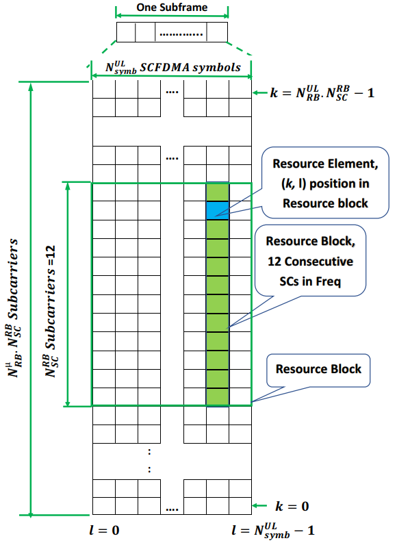
Subcarriers and Resource Blocks for given LTE Bandwidth
Below table shows the number of Subcarriers and Resource Blocks for given LTE Bandwidth.| Bandwidth | Resource Blocks | Sub Carriers (Uplink / Downlink) |
|---|---|---|
| 1.4 MHz | 6 | 72 / 73 |
| 3 MHz | 15 | 180 / 181 |
| 5 MHz | 25 | 300 / 301 |
| 10 MHz | 50 | 600 / 601 |
| 15 MHz | 75 | 900 / 901 |
| 20 MHz | 100 | 1200 / 1201 |
Back to Table of Contents [TOP]
LTE Frequency and Time Division Duplex (FDD & TDD) Schemes:
LTE uses orthogonal channels for information communication, which means it uses separate channels for uplink and downlink data/ packet transmission. There are two major schemes available to support it- (1) Frequency Division Duplex (FDD) and (2) Time Division Duplex (TDD).(1). Frequency Division Duplex (FDD):
A very popular duplex transmission scheme used in cellular network is Frequency Division Duplex (FDD) scheme. FDD supports simultaneous uplink and downlink transmission using different frequency channels / bands as shown in Figure (a) below. Uplink and downlink channels are generally separated by a sufficiently large margin (offset) to avoid interference.LTE also supports half-duplex FDD scheme at the user equipment (UE) side. In the half-duplex FDD scheme, uplink and downlink at a particular UE are separated in time as well as frequency, but the eNodeB (base station) still uses full-duplex FDD. For example, such scheme is supported by GSM cellular networks. Frequency and time resources allocation for Half-duplex scheme is shown in Figure (b) below.
(2). Time Division Duplex (TDD):
Time Division Duplex (TDD) scheme uses a single shared frequency, but the uplink transmission and downlink reception occur at different time slots as shown in Figure (c) below. This means the uplink and downlink can not occur simultaneously at the same time. In TDD scheme, time is divided in small intervals (time slots) and some of these slots are assigned for uplink transmission and some are assigned for downlink reception. Uplink transmission and downlink reception are separated by a sufficient guard time or guard interval. This time gap must be sufficient enough to completely receive the signal from transmitter and switching the transceiver to transmitting mode.TDD approach enables the UE for asymmetric data transmission and hence suitable for fulfilling the time-varying uplink and downlink traffic demands.

Comparison between FDD and TDD Schemes:
Both FDD and TDD are useful techniques and both are widely used in advanced wireless communication systems such as LTE. Below is a brief summary to compare both the techniques.
| Feature | Frequency Division Duplex (FDD) | Time Division Duplex (TDD) |
|---|---|---|
| Time/ Frequency Sharing | Different frequencies (bands) are used by the UE or eNodeB for transmit and receive purpose at a given instant of time. | Single shared frequency(band) is used by the UE or eNodeB for transmit and receive purpose at time shared basis. |
| Paired Frequency Channels | FDD needs paired frequency channels (spectrum) with sufficient frequency gap for simultaneous transmission and reception | TDD does not require paired frequency channels as both transmission and reception happen on the same frequency channel, but at different time intervals |
| Channel Estimation | Characteristics of uplink and downlink channels are different due to different frequency used. So separate channels estimation needed for uplink and downlink channels | Same frequency used in both directions, so the uplink channel estimation can be used for the downlink channel as well. |
| Asymmetry data support | Dynamically changing the UL/DL data traffic ratio is not possible due to frequency bands allocated by the regulatory authorities. | Dynamically changing the UL/DL data traffic ratio is possible based on the traffic volume demand in each direction at a given time interval. Large frequency gap will not limit the capacity in FDD. |
| Time/ Frequency gap | Sufficient Frequency gap is needed to avoid interference to adjacent bands. | Sufficient Guard time required to avoid interference between uplink and downlink transmissions. Large guard time may limit the capacity in TDD. |
| Continuous transmission | Continuous uplink and downlink transmission is possible in FDD. | Sufficient time needed to allow both uplink and downlink transmissions, so continuous transmission is not possible without gap |
| Hardware Cost | More cost effective than FDD as it requires less RF modules such as Synthesizer, Local Oscillators, filters etc. | FDD is costly due to more RF modules requirements. |
| Beam forming | TDD is more suitable for advanced antenna techniques such as Beam forming and Adaptive Antenna System due to it's uplink and downlink channel reciprocity. | FDD is not favorite candidate for Beam forming. |
LTE Type-2 Frame Structure for TDD:
Here are the details of TDD frame structure.
TDD Special subframe Details:
In LTE TDD duplex mode, transceiver needs to switch from Downlink to Uplink and Uplink to Downlink in between a frame. A Special subframe is needed when the transceiver makes switching from Downlink to Uplink. Special subframe is found on subframe #1 and subframe #6 in a 10 ms TDD frame. There are mainly three parts of a special subframe: DwPTS, GP and UpPTS. The length of these parts are configurable, but the total duration (length) is always 1 ms.
- Downlink Pilot Time Slot (DwPTS): DwPTS is always reserved for downlink transmission. It carries the reference signal and downlink control information.
- Guard Period (GP) : GP is required during the uplink and downlink transmission switching to compensate the small processing delay at the UE or eNodeB transceiver. The maximum supported size of the cell is determined by the length of this GP.
- Uplink Pilot Time Slot (UpPTS): UpPTS and the subframe immediately next to the special subframe are always reserved for uplink transmissionis. UpPTS is generally used for sounding reference signals (SRS) and RACH transmissions.

Here are the types of TDD frames.

TDD Uplink and Downlink Configurations:
| UL-DL configuration | DL to UL Switch-point periodicity | Subframe number | |||||||||
|---|---|---|---|---|---|---|---|---|---|---|---|
| 0 | 1 | 2 | 3 | 4 | 5 | 6 | 7 | 8 | 9 | ||
| 0 | 5 ms | D | S | U | U | U | D | S | U | U | U |
| 1 | 5 ms | D | S | U | U | D | D | S | U | U | D |
| 2 | 5 ms | D | S | U | D | D | D | S | U | D | D |
| 3 | 10 ms | D | S | U | U | U | D | D | D | D | D |
| 4 | 10 ms | D | S | U | U | D | D | D | D | D | D |
| 5 | 10 ms | D | S | U | D | D | D | D | D | D | D |
| 6 | 5 ms | D | S | U | U | U | D | S | U | U | D |
Back to Table of Contents [TOP]
LTE Downlink Physical Channels:
Downlink physical channels are basically a set of resource elements carrying information originating from higher layers to physical layer. These channels can be viewed as the interface defined between higher layer and physical layer. Below are the main downlink physical channels defined for LTE [Reference: 3GPP 36.211]:- — Physical Downlink Shared Channel (PDSCH)
— Physical Broadcast Channel (PBCH)
— Physical Multicast Channel (PMCH)
— Physical Control Format Indicator Channel (PCFICH)
— Physical Downlink Control Channel (PDCCH)
— Physical Hybrid ARQ Indicator Channel (PHICH)
— Enhanced Physical Downlink Control Channel (EPDCCH)
— MTC Physical Downlink Control Channel (MPDCCH)
— Short Physical Downlink Control Channel (SPDCCH)
Back to Table of Contents [TOP]
LTE Uplink Physical Channels:
Similar to Downlink physical channels, Uplink physical channels are also a set of resource elements carrying information originating from higher layers to physical layer. These channels can be viewed as the interface defined between higher layer and physical layer. Below are the main uplink physical channels defined for LTE [Reference: 3GPP 36.211]:- — Physical Uplink Shared Channel (PUSCH)
— Physical Uplink Control Channel (PUCCH)
— Physical Random Access Channel (PRACH)
— Short Physical Uplink Control Channel (SPUCCH)
Uplink Physical Signal:
In LTE, Uplink physical signal is used by the physical layer. Unlike the uplink physical channel, uplink physical signal does not carry any information originating from higher layers. The physical signal is known as Uplink Reference signal.Back to Table of Contents [TOP]
LTE Uplink Physical Shared Channels Processing:
A simplified overview of uplink physical channel processing is shown in below figure.
The processing of the baseband signal representing the LTE Uplink Physical Shared Channels is done in following major steps:
-
— Scrambling: For each codeword, block of m coded bits are scrambled with a UE-specific scrambling sequence prior to modulation.
— Modulation Mapper: The scrambled bits are further modulated to generate complex-valued symbols.
— Layer Mapper: After the modulation, the complex-valued modulation symbols are mapped onto one or several transmission layers.
— Transform Precoding: Transform precoding is done on the generate complex-valued symbols from the modulator output.
— Precoding: Precoding of the complex-valued symbols is done.
— Resource Element Mapper: These precoded complex-valued symbols are further mapped to resource elements
— SC-FDMA Signal Generator: Further, complex-valued time-domain SC-FDMA signal is generated for each antenna port.
Back to Table of Contents [TOP]
LTE Call Flow Process:
More details about LTE call flow will be discussed here.
Back to Table of Contents [TOP]
LTE Advanced Techniques:
Here we will discuss about the advanced LTE topics. More details coming soon.Back to Table of Contents [TOP]
Comments
Post a Comment